 Cable Fault
Underground cables are usually used in highly populated areas. They are extremely important to carry power especially to those, which need high voltages like industries and other important support services. To ensure the continuity of supplying power to such places, routine tests and maintenance are performed. Those processes decrease the possibility of faults. Minimizing feeder output during a fault is the major goal and the crucial factor in deciding the procedure for a cable fault location. The responsibility of providing power also lay depend on repairing cable fault in the shortest possible time by using a well-equipped test van.
Early detection of cable damage by means of fast testing, inexpensive repair of cable faults are never totally avoidable. The detection and repair of faults in cable networks is now an important economic factor. The cable fault technician should receive the allowance from the switchman for the faulty cable that is isolated and grounded from both sides. Then, a caution boards are put in both sides, which indicate that cable is under test. Potential and current transformers should be disconnected from cable if any. Faults are located using pulse techniques and that will be described later.
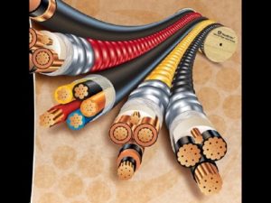
Cables can be defined as the physical media used to transmit the electrical power.
Any metallic element has the ability of carrying the electricity. However, the efficiency of carrying the electricity varies from one element to another. The cable efficiency is measured depending on the power flow resistance. The other name of cables is conductors
Any one dealing with cable fault location should have the enough knowledge about cables. However, the insulation of voltage medium of cable is increasingly being made of synthetic materials. Paper-insulated cables are used at medium voltage
Three-core pilca
It has three copper or aluminum cores with layers of oil-impregnated-paper insulation. Then, layers of oil paper belting insulation over the cores. After that, lead or aluminum sheath, steel tape or wire armouring. Finally, PVC protection overall.
Three-core xlpe:-
Cross-linked polyethylene (XLPE) insulation in now normal cable has either three-core or single-core. Xlpe screen is made of copper wires applied over the semiconducting layer on the xlpe insulation, three core pvc insulated with steel wire-armouring and pvc sheath overall. It’s the lowest cost compared with equivalent materials, in 13.8 k.v & 34 k.v.
Three-coreX300mm² cable are used but, for 69 k.v the standard is single core 1x 400 mm² or 1x 600 mm², and the type of conductor material is aluminum. For the 115 k.v, 230 k.v & 380 k.v oil-filled cables are used always they are single core with conductors. The kits for termination and splicing for medium voltage (13.8 k.v – 34 k.v) are heat shrinkable material, for H.V 69 k.v and above they have their special kits.
Current capacity of the conductors:
Depending on the nature of the conductors, they have different current carrying capacity. The gold as an example has the largest capacity but it is very expensive element. In fact, the most famous used conductors in the word are cupper and aluminum conductors. The cupper has more current capacity and flexibility than aluminum. However, the aluminum is cheaper. Theoretically, the current capacity of the conductors depends directly on the cross sectional area of the conductors.
What Will Happen If the Conductor Carry More Current Than Its Capacity Indicates?
If the conductor is forced to carry more power than its capacity, this power will transfer from electrical power to thermal power (as heat), which will heat up the conductor and finally fault may occur on the cable.
Insulations:
Any non-conducting material can be considered as insulation. As conductors have different conducting ability, the insulations have different insulation ability. The insulation plays significant role in power systems. It is used to protect the user from electrical shuck that may happen due to touching of the conductors. In addition, it is used to protect the conductor from the exterior weather factors. Some of the cables use also cretin coating and reinforcement, which is used for exterior physical protection of the conductor. As the applied voltage on the cable, increase, the better insulation technique should be used. There are different types of insulation technique some them use plastic, paper, oil, and gas as insulation media.
What is a fault?
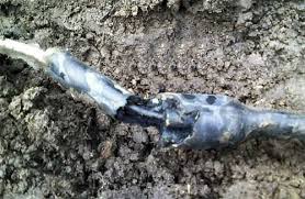
A fault could perhaps be defined as any defect, weakness, inconsistency or non-homogeneity that affects the performance of cable, although the most common type of the fault are either contact fault or breaks, these can occur in isolation or combination.
Faults are classified in to :
1- Contact fault
This is a short or shunt fault, it happens due to connection or part connection between one core and another or between cores and the metallic sheath this described as a short or shunt fault
2-Ground fault
It is a contact between core or cores and mass of earth, or between metallic sheath and the mass of earth. This often occurs on unshielded multicore cables.
Faults type
Conductor fault
It is an open circuit fault or series fault; it is also called the break in conductor, conductor physically broken, customer has outage but, circuit breaker or fuse not blown. This type of fault may come from pulling the joints through mechanical damages or in case of very high resistance fault. Prelocation can be determined by pulse reflection method. The surge wave front from the surge generators is immediately reflected back from a fault but with opposite polarity.
T is the time interval between the first pulse and its first arrival back from the fault.
Insulation fault
It is a direct contact between conductors, conductor to ground, and this type of fault always coming by damaging the insulation of cable through many reasons
Pre-location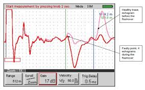
A pre-location is the test that is carried out on the cable termination, to measure the distance to the fault point. Low- impedance cable fault can easily be detected as a reflection, where high impedance fault reflect the pulse weakly, or not at all which make the fault point impossible to detect. The result will usually be approximate on along cable. This is due to inherent errors in the actual test and errors in the measured length of the cable over its route. With most of pre-location an error of between 0.1 and 0.5 percent, therefore in most cases, a pre-location can only be expected to give a suspect area. The use of traveling wave methods has eliminated the complication of equivalent length calculations since the velocity of propagation of electromagnetic waves is only a function of the cable dielectric. The measurement should be accurate as conditions will allow.
THERE ARE SEVERAL METHODS OF PRELOCATION
Pulse reflection method
Measuring principle
For the prelocation of the fault point in an electrical cable by pulse reflection method, the pulse reflection method uses pulse of suitable shape and width, which are transmitted into the cable to be measured in periodic sequence irregularities in the otherwise homogenous wave resistance cause reflection which are caught at the start of the cable. The pulses which are fed in at one end of the cable and travel along the cable with a certain propagation velocity (Vp) a change in the characteristic impedance (Z) of the cable reflects them to the start end of the cable. In other hand, the pulses traveling from the reflection point back to the beginning of the cable is called pulse echo. The time delay between sending the pulse and receiving it back in a faulty phase is used to calculate the distance to fault point. Following the same way in sound phase used to determine the total length of the cable. Only low resistance fault and breaks (open circuit) can be located with the pulse reflection method, also coupling faults can be located.
Distance = 0.5 x (known velocity in m/u sec x time in u sec)
Velocity propagation V/2
For cable fault location by the pulse reflection method, the velocity propagation of electrical impulse in cables has to be known as precisely as possible in order to obtain maximum accuracy. This Vp depends on the dielectric of the cable insulation on the one hand, and on the frequency attenuation shape of cable on other hand. Since in this test mode the time between transmission and return of the test pulse is measured.
T X VP
L = ———
2
ARC Reflection Method
Measuring principle
The basic concept of arc reflection method is to influence a high impedance fault in such a way that it has low impedance for a limit period. During this time, it can be located using the normal pulse reflection method. To do this, an arc (flash over triggered by surge pulses) is produced at the fault point for a specific duration.
Measurement
This prelocation method is used in cases where it is not possible to produce a stable low fault resistance, by means of DC test instrument. However, the generation of an arc at the fault depends on the type of cable insulation on the one hand and on the magnitude of arc current on other hand.
The output voltage of DC test instrument is increased until the fault ignites, when the fault ignites, an arc is generated at the fault and hence a low resistance value is created. Whereby the arc resistance is considerably decreased, for duration of approx, 1.5 seconds. The test duration is limited to 1.5 seconds, within this duration, the arc is measured by the usual method using a pulse reflection instrument via an isolation capacitor and the fault position is determined, subsequently the fault distance is determined from the recorded trace.
ARM Pulse Method
The ARM method which already approved for many years is redeveloped into the new (ARM PLUS) technology. This technology has now already proven its excellent suitability. The arm plus procedure require only a few milliseconds time and duo to the flash technology in combination with the reliable and fast trigger circuit. Only one measurement is required to receive a perfect display of the reflectogram or trace to locate the fault. Timing adjustments or similar calibration procedures are not required and no special skills are expected from the operator. Unlike other faults location technologies, this one shot technology prevents the change or “self repairs” of critical faults and provides immediate and reliable results for the location of the fault. Resulting from the high accuracy of the pre-location the pinpointing.
Procedure will also require comparatively less time and the stress caused to the cable byThe complete fault location procedure is accordingly low.
Second Impulse Method
The most advanced and latest development of cable fault pre-location methods is the secondary impulse method. The special features of this measuring method are simple operation, versatile application and easy interpretation of the echograms. The surge voltage generator with connected pulse shaper is used to arc the high resistance fault. The echo meter is triggered synchronously and stores the new trace in the memory. The new trace indicates a strong negative reflection on the fault point which has become low resistance during arcing. The simultaneous display of a previously stored healthy trace simplifies the interpretation
Decay Method
The decay method is exclusively suitable for high-voltage cables, the method enables fault location of intermittent faults or flash-over faults up to highest breakdown voltage levels.
The high voltage test set sends direct voltage to the cable core under test, high voltage coupling takes place with the capacitive coupler; the high voltage test set ignites the fault location for a short time, the transient waves caused by this, and recorded by the capacitive coupler and fed to the TDR. The transient recorder stores the incoming signal and displays for analysis.
Decay plus method is new prelocation technology analyses the breakdown of the fault during the high voltage application and follows directly with the above (arm plus) method into the still discharging breakdown. This new technology delivers a trace identical and with the same informative quality as the arm plus method. Reflectogram taken with the decay plus method can be directly compared with those pictures taken by the arm plus method. Resulting the decay plus method provides perfect arc reflection traces up to 80 k.v and extends the existing prelocation voltage range to a new limit which fulfils almost technical requirement.
Pin Pointing
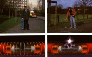
Pinpointing is the final step of locating cable faults, it is the application of a test that carried out to determine the precise locations of the fault point, once the prelocation of fault point & the cable route tracing have been determind, such tests are carried out directly over the cable. The majority of faults on high voltage power cable are pinpointed by detecting the acoustic signal generated when the fault spark gap breaks down either from the application of voltage impulse from a surge generator or high voltage DC from pressure test set.
Several Methods of Pinpointing are as follow
- ACCOUSTIC DETECTOR
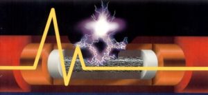
The most frequently method used is acoustic pinpointing in which a surge generator is connected to the defective cable. A 15 KV DC is applied to the effective core and so using the receiver, a sound of cracking is heard and the exact location of fault is determined using accoustic the maximum accoustic sound will be obtained at the fault point. The importance of pinpointing stage cannot be over-emphasised (e.g.) prolonged preconditioning should be avoided, once a fault develops into a very low resistance. The condition it will (short out) the spark gap making it impossible to generate an acoustic signal.
The surge wave receiver is a directional acoustic listening device for the pinpointing of flash-over power cables. The location of the buried cable can be determined by the direction and intensity of the magnetic field, produced by the impulse current of a surge generator (thumper). With barograph-indicator of the acoustic (digiphne), the intensity of the strength of the magnetic field can be measured. This has a maximum directly above the cable. The acoustic locating is done by measuring the flash over noise. A switchable flitter is built-in to optimize the measurement. The bandwidth of this filter is designed to minimize ambient noise (wind-vehicles) the fault location can be done either by the intensity of the sound volume or by the distance measurement.
- AUDIO FREQUENCY METHOD
Short circuit fault can be determined using the audio frequency method. Frequency sound will be dropped after passing the fault point. Further more the fault point can be check from both sides for conformation.
TWIST METHOD
The twist method is the best way for pinpoint of completely short circuit fault between cores (0 Ω), since a surge, generator and accoustic method are failed. Frequency sound will be completely dropped after passing the fault point. For more confirmation, pulse reflection techniques can be used to locate the distance of fault point from both ends, since the resistance is (0Ω).

